This project is still alive! 🙂
I know it’s been a while since posting an update on this project. I’ve picked it back up and been working on it on and off for the past few months.
The focus has still remained on the DN-2000F mk II model, and I believe I now have the hardware side of it finalised.
Hardware
After much research with various USB UART controllers, the SiLabs CP2102 seemed to be the best choice. You can pick them up for cheap from many eBay sellers and come on PCB boards that have a USB connector and breakout pins.
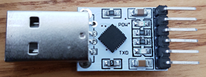 – SiLabs CP2102 USB to UART
There are 6 breakout pins:
– 3.3V
– RST
– TXD
– RXD
– GND
– 5V
The Denon DN2000F mk II remote, the RC-35B, runs on 5 volts so we can power it from the 5V pin. This will only work if the USB port is capable of delivering ~150mA, which standard USB ports on a computer will be able to provide. If using a hub, ensure it’s a powered USB hub.
Other required components:
– 1x mini DIN male to male cable
– 1x MC3487 IC (DIP)
– 1x 10nF capacitor
– 2x 1KΩ resistors
– Push-in terminal blocks
– Jump wires
You’ll also need a breadboard, I’m using a KandH AD-14.
Cut one end off the 8 pin male to male mini DIN cable and strip back the wires. You’ll then need to note which colour corresponds to which pin.
 – Looking at the male mini DIN plug. Pins have been numbered.
In the case of my cable:
| Pin |
Colour |
Notes |
1 |
Brown |
Ground |
2 |
Red |
5V |
3 |
Black |
Ground |
4 |
Purple |
RX |
5 |
Orange |
5V |
6 |
Blue |
TX |
7 |
Green |
TX |
8 |
Yellow |
RX |
Powering the RC-35B
Pins 1 and 3 are interconnected inside the RC-35B, as are pins 2 and 5. Pair (or twist) the brown and black wires together. Do the same with the red and orange wires.
Connect the brown and black wires to GND and the red and orange wires to the 5V breakout pins.
MC3487
The MC3487 is used to convert between TTL and RS-422 signals.
The MC3487 operates on a 5V supply. Connect VCC (pin 16) to the 5V breakout pin. You should also add a capacitor (10nF) between VCC and GND (pin 8). Connect GND to the GND breakout pin.
Connect the inverting OUTPUTS C (pin 11) to the green wire and connect the non-inverting OUTPUTS C (pin 10) to the blue wire. Connect INPUT C (pin 9) to the TXD breakout pin.
Connect INPUT A (pin 1) to the the yellow wire via a 1KΩ resistor and connect INPUT B (pin 7) to the purple wire, again via a 1KΩ resistor. Connect OUTPUT A (pin 2) to the RXD breakout pin.
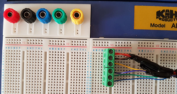
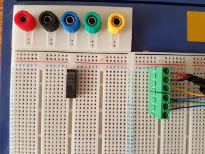
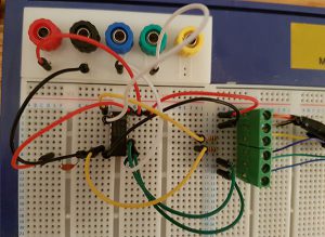
How it looks on a breadboard
Note that the edge terminals are connected to the following on the USB breakout:
RED: 5V
BLACK: GND
BLUE: TXD
GREEN: RXD
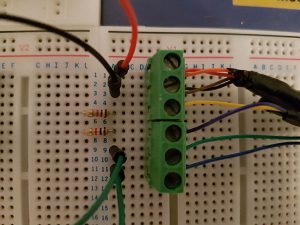
I started off with inserting the mini DIN cable wires in to terminals and plugged them in to the breadboard:

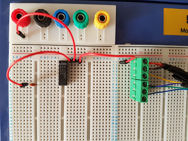
Then plugged in the MC3487:
Connected 5V to the MC3487 and added in the decoupling capacitor. I also connected the 5V to the red and orange wires:

Next, the GND is connected GND on the MC3487 and the black and brown wires:
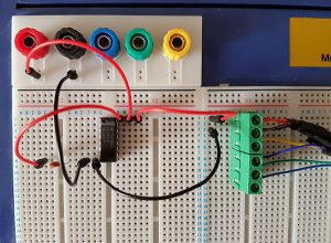
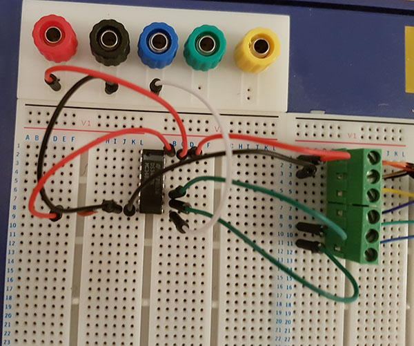
Connected the OUTPUTS C of the MC3487 and INPUT C to the TXD breakout pin:

Plugged in 1KΩ resistors for the yellow and purple wires:
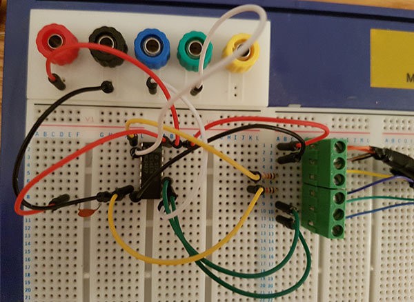
Connected INPUT A and B on the MC3487 and connected OUTPUT A to the RXD breakout pin:
And that’s it.
The next post will be around the software and looking how it can interact with the likes of Mixxx.